Pages

Popular Posts

Saturday 22 February 2014

Engine..

Aviation Models
Home Page
Engine Index
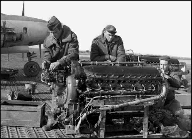
Mechanics working on an Allison V-1710 engine for a Lockheed P-38 Lightning .
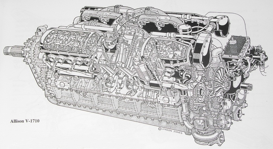
    The only American liquid-cooled engine to see service in World War II was the Allison V-1710. It was one of the most important large USA aero engines, with over 70,000 engines produced from the time of the first in 1931 to the last in 1948. The engine was produced for several important fighters of WWII, including the P-38 Lightning P-39 AiracobraP-40 WarhawkP-51A MustangP-63 KingcobraP-82 Twin Mustang and the Consolidated XA-11A, an experimental attack version of theConsolidated P-25. Allison was an Indianapolis firm that had done well in a small way with Libertyengine modifications and with reduction gears for others' engines.
    Around the time the Army was washing its hands of the Curtiss Conqueror, Allison began to develop its own engine, at the request of Allison General manager Norm Gilman. The target was 1,000 hp, and Allison intended that the engine should be large enough to deliver this power easily. A successful V-1710-A was test run in 1931 and delivered 650 hp at 2,400 RPM on 80-octane fuel. Development proceeded slowly until the Navy entered the picture. The Navy, while not losing its attachment to air-cooled power plants for airplanes, it still needed liquid cooling for dirigibles. The Navy requested eliminating the supercharger (rotary induction blower) in favor of two carburetors placed in the Vee of the engine. A significant redesign was undertaken by R.M. Hazen in 1936. This "C"-model passed its 150 hour type acceptance test in 1937, establishing a rating of 1,000 hp at 2,600 rpm at sea level. A number of incremental improvements were made during the life of the "C"-model, eventually leading to "C"-models with takeoff ratings of 1,150 hp at 2,950 rpm and supporting 3,500 rpm for overspeed during dives.
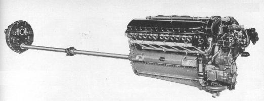
The V-1710-E18 & E19 engine with extension shaft and outboard reduction
gear box used on the P-39 Airacobra.

    The production Allison turned out to be the sturdy and reliable powerplant that its designers strived for. The only thing that stood between the Allison and real greatness was its inability to deliver its power at sufficiently high altitudes. This was not the fault of its engineers. It resulted from an early Army decision to rely on turbo-supercharging to obtain adequate power at combat heights. Even this decision was not a technical error—a turbo-supercharged Allison was as good as any high-altitude engine. The trouble was that the wartime shortage of alloying materials, especially tungsten, made it impossible to make enough turbo-superchargers for the entire Allison production. Therefore, bombers such as the Boeing B-17 Flying Fortress and Consolidated B-24 Liberator, running radial engines, were given priority over all others in regards to turbo-superchargers.
    The few turbo-supercharged Allisons that were made, were allocated to P-38s, making the high-altitude performance of that plane its best feature. All early P-40s were equipped with gear-driven superchargers, and as a result, were never first-class fighter planes. Donaldson R. Berlin, the P-40'sdesigner, has said that P-40s experimentally equipped with turbo-superchargers outperformed Spitfiresand Messerschmitts and that if it had been given the engine it was designed for, the P-40 would have been the greatest fighter of its era. Some may say this is an exaggeration by Donaldson Berlin, because when Rolls-Royce Merlin engines were installed in Curtiss P-40Fs and P-40Ls, they were still no match for the best fighters of the day. It wasn't until the XP-40Q was modified with a "bubble" canopy, cut-down rear fuselage, wing radiators, clipped wing tips, a four-blade propeller, water injection and weight reduced to 9,000 lb that the XP-40Q attained a maximum speed of 422 mph. However, there is no doubt that the deletion of the turbo-supercharger limited the P-39 Airacobra to low-altitude operations.
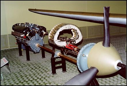
The V-1710-85 engine with extension shaft and outboard reduction gear box used on the P-39 Airacobra(Photo: National Museum of the US Air Force.)
    Had Allison's engineers been able to put the effort into gear-driven superchargers that Pratt and Whitney and Rolls-Royce did, it might have been a different story. As it was, there can be little doubt that the V-1710 had more potential than was actually exploited.
    Allison became a part of general motors in 1929, and the firm was a GM component known asDetroit Diesel Allison Division until 1995. The company was then acquired by Rolls-Royce Group plc and is now a subsidiary of the Rolls-Royce Corporation.


Specifications:
Allison V-1710-G6
Date:1941
Cylinders:12
Configuration:V type, Liquid cooled
Horsepower:1,250 hp (932 kw)
R.P.M.:3,200
Bore and Stroke:5.5 in. (140 mm) 6 in. (152 mm)
Displacement:1,710 cu. in. (28 liters)
Weight:1,595 lbs. (707 kg)

Sources:

Ed. Ralph D. Bent, James L. McKinley. Aircraft Power Plants by the Northrop Aeronautical Institute. (New York: McGraw Hill, 1955.)
Herschel Smith. A History of Aircraft Piston Engines. (Manhattan, Kansas: Sunflower University Press, 1993.)
Ed. Glenn D. Angle. Aerosphere, 1943. (New York: Aerosphere Inc.)
Unlimited Excitement IIc; The Allison V-170 Engine. www.unlimitedexcitement.com. 2005.
National Museum of The United States Air Force; Allison V-1710 Enginewww.wpafb.af.mil. 2005.
Wing DihedralAviation Models
Home PageTheory Index
    Wing Dihedral is the upward angle of an aircraft's wing, from the wing root to the wing tip. The amount of dihedral determines the amount of inherent stability along the roll axis. Although an increase of dihedral will increase inherent stability, it will also decrease lift, increase drag, and decreased the axial roll rate. As roll stability is increased, an aircraft will naturally return to its original position if it is subject to a brief or slight roll displacement. Most large airliner wings are designed with dihedral.
    On low-wing aircraft, the center of gravity is above the wing and roll stablity is less pronounced. This factor requires the use of greater dihedral angles in low-wing airplanes.
    On high-wing aircraft, the center of gravity is below the wing, so less dihedral is required.
    On low-wing aircraft with wing dihedral, when a wing rolls downward, the relative wind on the descending wing becomes a component of the forward motion of the airplane and the downward motion of the wing. This produces a higher angle of attack on the descending wing and consequently more lift.
    Highly maneuverable fighter planes have no dihedral and some fighter aircraft have the wing tips lower than the roots, giving the aircraft a high roll rate. A negative dihedral angle is called anhedral. The AV-8B Harrier II above has a negative dihedral or anhedral
Wind EffectAviation Models
Home PageTheory Index
    During flight, one of the main considerations that will affect an aircraft is the motion of the wind. Referred to as wind effect, the speed and direction of the wind will alter the progress of any aircraft in flight. Although an aircraft has its own means of propulsion, the pilot must compensate for the wind speed and direction, in order for an aircraft to maintain the desired course.
    If we were to take a simple balloon, with no means of propulsion, and let it float freely in the air, the balloon will drift at the same speed and direction in which the wind is moving. If the air is moving at 10 mph in a southerly direction, after one hour, the balloon will drift 10 miles south.
    Now if we were to fly an airplane straight and level at 100 mph for one hour heading due east, the aircraft will be 100 miles east of its starting point after one hour, but it will also drift south 10 miles (the same as the balloon), if the pilot does not correct for the wind. When the wind is moving towards an aircraft from an angle, this will cause what is referred to as wind drift. For more information on this topic, refer to the page on wind drift.
    Again if we were to take the same balloon, (with no means of propulsion, and let it float freely in the air), with the air moving at 10 mph in an easterly direction, after one hour, the balloon will drift 10 miles east. Now if we were to fly an aircraft at 100 mph for one hour, heading due east, the aircraft will be a distance of 110 miles east of its starting point. The aircraft was again affected by the wind just as the balloon was. The aircraft flew 100 mph under its own power, but it also was able to gain an additional 10 miles in distance, because it was carried along by the wind, that was moving as the same direction as the aircraft. This is called a tailwind.
    If the aircraft were to fly west under the same conditions, after one hour the aircraft would have flown only a distance of 90 miles. This time the aircraft was flying directly into the wind and the wind speed is subtracted from the aircraft speed. In this case the aircraft is said to be flying into aheadwind.
    When a headwind is subtracted or a tailwind is added to the speed of an airplane, this is called the wind component and will affect only the ground speed and not the actual airspeed of the aircraft. In this example, the airspeed will always read 100 mph, but if the aircraft is affected by a tailwind or headwind component, we must add or subtract the wind speed to find the actual progress or ground speed of the aircraft. For instructions on how to calculate this, refer to the page on ground speed.
Wind DriftAviation Models
Home PageTheory Index
    Drift is caused by the wind effect on an aircraft and is defined as the angle between the aircraft heading and the aircraft track.1
    The direction in which an aircraft is pointed is called the heading. The actual path in which an aircraft travels over the ground is called the track. If an aircraft is flying straight into the wind, the aircraft true (geographical) course is calculated to be the same as the aircraft track.
    However, if the wind is coming at an aircraft from an angle (crosswind), the track and desired course will deviate. The angle between the desired course and the track is known as the drift angle. In order to maintain the aircraft track on the desired course, the heading must be corrected left or right, depending on the direction of the crosswind.
    If a crosswind is coming towards an aircraft from the left, the aircraft will drift to the right of the desired course. In order to counteract for drift, the aircraft must be turned to the left or into the wind. This is known as the wind correction angle and is expressed in terms of degrees.
The Swept WingAviation Models
Home PageEngine Index

    The concept of sweeping an aircraft's wings is to delay the drag rise caused by the formation of shock waves. The swept-wing concept had been appreciated by German aerodynamicists since the mid-1930s, and by 1942 a considerable amount of research had gone into it. However, in the United States and Great Britain, the concept of the swept wing remained virtually unknown until the end of the war. Due to the early research in this area, this allowed Germany to successfully introduce the swept wing in the jet fighter Messerschmitt Me-262 as early as 1941.
    Early British and American jet aircraft were therefore of conventional straight-wing design, with a high-speed performance that was consequently limited. Such aircraft included the UKGloster Meteor F.4 , the U.S. Lockheed F-80 Sooting Star and the experimental U.S. jet, the Bell XP-59A Airacomet.
    After the war German advanced aeronautical research data became available to the United States Army Air Force (USAAF) as well as Great Britain. This technology was then incorporated into their aircraft designs. Some early jets that took advantage of this technology were the North American F-86 Sabre, theHawker Hunter F.4 and the Supermarine Swift FR.5.
    Not to be outdone, the Soviet Union introduced the swept wing in the Mikoyan Mig-15 in 1947. This aircraft was the great rival of the F-86 during the Korean War.
Relative WindAviation Models

Theory Index
    The relative wind is a relationship between the direction of airflow and the aircraft wing. In normal flight circumstances, the relative wind is the opposite direction of the aircraft flight path.
        1. If the flight path is forward then the relative wind is backward.
        2. If the flight path is forward and upward, then the relative wind is backward and downward.
        3. If the flight path is forward and downward, then the relative wind is backward and upward.
    Therefore, the relative wind is parallel to the flight path, and travels in an opposite direction.1
    Also relative wind can created by a stationary object and the motion of the air around it, as when an aircraft is pointed down a runway for takeoff. This is why takeoffs are normally into the wind.
    During takeoff, when the aircraft is stationary, the relative wind would be the motion and direction of the airflow around the aircraft created by the wind. As the airplane accelerates down the runway, the wind and motion of the aircraft are combined to create relative wind. Once the aircraft becomes airborne, only the motion of the aircraft produces relative wind, and the relative wind becomes opposite and parallel to the flight path of the aircraft.
    Although the wind can affect the ground speed and aircraft drift, the relative wind will always remain opposite and parallel to the aircraft wing.
    Refer to the page on angle of attack for comparison.
Aviation Models

Engine Index
    Laminar Flow is the smooth, uninterrupted flow of air over the contour of the wings, fuselage, or other parts of an aircraft in flight. Laminar flow is most often found at the front of a streamlined body and is an important factor in flight. If the smooth flow of air is interrupted over a wing section, turbulence is created which results in a loss of lift and a high degree of drag. An airfoil designed for minimum drag and uninterrupted flow of the boundary layer is called a laminar airfoil.
    The Laminar flow theory dealt with the development of a symmetrical airfoil section which had the same curvature on both the upper and lower surface. The design was relatively thin at the leading edge and progressively widened to a point of greatest thickness as far aft as possible. The theory in using an airfoil of this design was to maintain the adhesion of the boundary layers of airflow which are present in flight as far aft of the leading edge as possible. On normal airfoils, the boundary layer would be interrupted at high speeds and the resultant break would cause a turbulent flow over the remainder of the foil. This turbulence would be realized as drag up the point of maximum speed, at which time the control surfaces and aircraft flying characteristics would be affected. The formation of the boundary layer is a process of layers of air formed one next to the other, i.e.; the term laminar is derived from the lamination principle involved.
History of Laminar Flow
    The P-51 Mustang was the first aircraft intentionally designed to use laminar flow airfoils. However, wartime NACA research data shows that Mustangs were not manufactured with a sufficient degree of surface quality to maintain much laminar flow on the wing. The RAF found that the Bell P-63, despite being designed with laminar airfoils, also was not manufactured with sufficient surface quality to have much laminar flow.
    The Mustang a mathematically designed airplane and the wing foil that was to be classified as a "semi-empirical venture" by the British was cleared for adoption on the new design. The wing section would be the only part of the fighter which would be tested in a wind tunnel prior to the first test flight. Due to the speculation of the success of the radical foil, the engineering department was committed to adopt a more conventional airfoil within thirty days of the tests in the event the wing did not come up to specifications. A one quarter scale model of the wing was designed and constructed for tests in the wing tunnel at the California Institute of Technology.
    The use of this airfoil on the Mustang would greatly add to the drag reducing concept that was paramount in all design phases of the airplane. The few applications of this foil, prior to this time, had been handbuilt structures which were finished to exacting tolerances. An absolutely smooth surface was necessary due to the fact that any surface break or rough protrusion would interrupt the airflow and detract from the laminar flow theory. Because of the exactness required, the foil had been shelved by other manufacturers due to the clearances and tolerances which are used in mass production. The engineers at NAA approached this problem with a plan to fill and paint the wing surface to provide the necessary smoothness. The foil which was used for the Mustang had a thickness ratio of 15.1 percent at the wing root at 39 percent of the chord. The tip ratio was 11.4 percent at the 50 percent chord line. These figures provided the maximum thickness area at 40 percent from the leading edge of the wing and resulted in a small negative pressure gradient over the leading 50-60 percent of the wing surface.
    The B-24 bomber's "Davis" airfoil was also a laminar flow airfoil, which predates the Mustang's. However, the designers of the B-24 only knew that their airfoil had very low drag in the wind tunnel. They did not know that it was a laminar flow airfoil.
    There were several aircraft modified by NACA, in the late 1930s, to have laminar flow test sections on their wings. Hence, such aircraft as a modified B-18 were some of the first aircraft to fly with laminar flow airfoils.
    The boundary layer concept is credited to the great German aerodynamicist, Ludwig Prandtl. Prandtl hypothesized and proved the existence of the boundary layer long before the Mustang was a gleam in anyone's eye.


    Example: First, lets get more specific about what laminar flow is. The flow next to any surface forms a boundary layer, as the flow has zero velocity right at the surface and some distance out from the surface it flows at the same velocity as the local outside flow. If this boundary layer flows in parallel layers, with no energy transfer between layers, it is laminar. If there is energy transfer, it is turbulent.
    All boundary layers start off as laminar. Many influences can act to destabilize a laminar boundary layer, causing it to transition to turbulent. Adverse pressure gradients, surface roughness, heat and acoustic energy all examples of destabilizing influences. Once the boundary layer transitions, the skin friction goes up. This is the primary result of a turbulent boundary layer. The old lift loss myth is just that—a myth.
    A favorable pressure gradient is required to maintain laminar flow. Laminar flow airfoils are designed to have long favorable pressure gradients. All airfoils must have adverse pressure gradients on their aft end. The usual definition of a laminar flow airfoil is that the favorable pressure gradient ends somewhere between 30 and 75% of chord.
    Now Consider the finish on your car in non-rainy conditions. Dust and leaves have settled on the hood's paint. We go for a drive. At once the leaves blow off. But the dust remains. We speed up. Even if we go very fast, the dust remains because of the thin layer of air that moves with the car. If you drive with dew on your car, the dew will not so quickly be blown dry where the air flow has this thin laminar layer. Downstream, where the laminar flow has become turbulent, the air flow quickly dries the dew.
    In the fifties this was dramatically shown in a photograph of the top of a sailplane wing (in-flight) that had dew on it. A few tiny seeds had landed on forward area the wing while on the ground. In flight these seeds, tiny though they were, reached through the laminar layer and caused micro-turbulence causing the dew to be blown dried in an expanding vee shaped area down stream of each tiny seed.

Additional information
Profile drag
    This comprises two components: surface friction drag and normal pressure drag (form drag).
    Surface friction drag: This arises from the tangential stresses due to the viscosity or stickinessof the air. When air flows over any part of an aircraft there exists, immediately adjacent to the surface, a thin layer of air called the boundary layer, within which the air slows from its high velocity at the edge of the layer to a standstill at the surface itself. Surface friction drag depends upon the rate of change of velocity through the boundary layer, i.e. the velocity gradient. There are two types of boundary layer, laminar and turbulent. Although all combat aircraft surfaces develop a laminar boundary layer to start with, this rapidly becomes turbulent within a few per cent of the length of the surface. This leaves most of the aircraft immersed in a turbulent boundary layer, the thickness of which increases with length along the surface. The velocity and hence pressure variations along the length of any surface can have adverse effects on the behavior of the boundary layer, as will be discussed later.
    Surface friction drag can amount to more than 30% of the total drag under cruise conditions.
    Normal pressure drag (form drag): This also depends upon the viscosity of the air and is related to flow separation. It is best explained by considering a typical pressure distribution over a wing section, first at low AOA and then at high AOA.
    At low AOA the high pressures near the leading edge produce a component of force in the rearward (i.e. drag) direction, while the low pressures ahead of the maximum thickness point tend to suck the wing section forward, giving a thrust effect. The low pressures aft of the maximum thickness point tend to suck the wing rearwards, since they act on rearward-facing surfaces. Without the influence of the boundary layer, the normal pressure forces due to the above drag and thrust components would exactly cancel.
    There is a favorable pressure gradient up to the minimum pressure point, with the pressure falling in the direction of flow. This helps to stabilize the boundary layer. Downstream of the minimum pressure point, however, the thickening boundary layer has to flow against an adverse pressure gradient. Viscous effects reduce momentum within the boundary layer, and the thickness of the layer further increases so that the external flow sees a body which does not appear to close to a point at the trailing edge. A narrow wake is formed as the boundary layer streams off the section. This prevents the pressures on the aft-facing surface of the wing section from recovering to the high value obtaining near the stagnation point on the leading edge, as they would have done if a boundary layer had not formed. There is thus a lower than expected pressure acting on the aft facing surface, giving rise to normal pressure drag. In the low-AOA case this component is small, most of the profile drag being made up of surface friction drag.
    As the AOA of the wing section is increased, the point of minimum pressure moves towards the leading edge, with increasingly high suction being achieved. This means that the pressure then has to rise by a greater extent downstream of the minimum pressure point and that the length of wing surface exposed to the rising pressure is increased. The resulting adverse pressure gradient becomes more severe as AOA is increased. This has serious implications for the boundary layer, which is always likely to separate from the wing surface under such conditions.